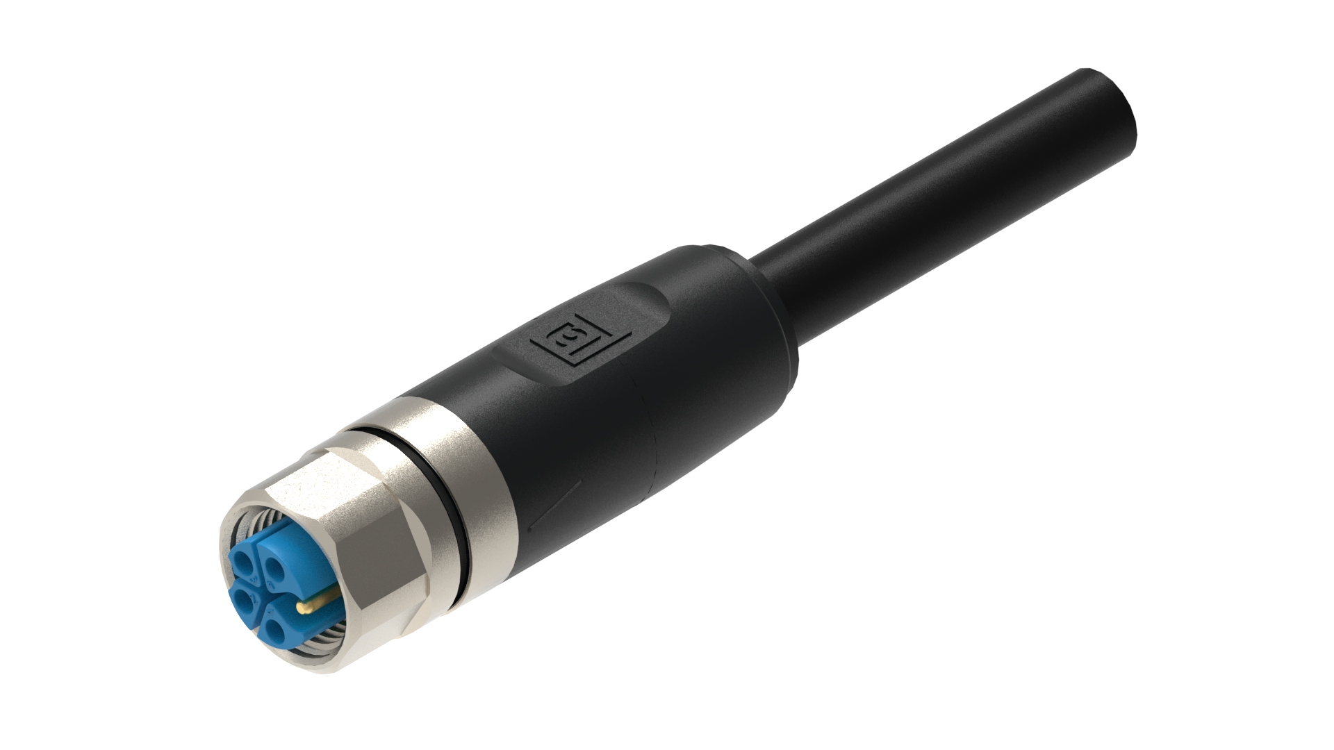
M12 Power RAILWAY | Cordset | Female Straight → Open End, 5-pin K-code, LSZH (1.50 mm2) 16 AWG, 630 V / 16 A, NFPA 130
M12 Power RAILWAY | Single-Ended Cordset | M12 Female Straight, #Contacts 5, K-code → Open End | Cable: Black LSZH; 1.50 mm2 (16 AWG) | 630 V / 16 A, NFPA 130
- Availability
- Global
- Status
- Active
- Orderable items
- 7
Part numbers
RKT 5K-1037 is a product family. Each item number below is a separate orderable part — colour, put-up and length differ.
| Item # | Item Description | Cable Length | Order |
|---|---|---|---|
| 934849431 | RKT 5K-1037/2 M | 2 m | Order online |
| 934849433 | RKT 5K-1037/3 M | 3 m | Order online |
| 934849434 | RKT 5K-1037/5 M | 5 m | Order online |
| 934849435 | RKT 5K-1037/7,5 M | 7.5 m | Order online |
| 934849429 | RKT 5K-1037/10 M | 10 m | Order online |
| 934849430 | RKT 5K-1037/15 M | 15 m | Order online |
| 934849432 | RKT 5K-1037/20 M | 20 m | Order online |
Specifications
Information
| Product Family | Power Connector |
|---|---|
| Side 1 Product Sub Family | M12 Power RAIL |
| Connector Type | Cordset, single ended |
| Connector Sub Type | Power RAIL |
| Side 1 Type of Contact/Gender | Socket Contact / Female |
| Connector Design | Molded | M12 Female | Straight |
| Number of Pins | 5 (4+PE) |
| Coding, Side 1 | K |
| Shielding Type | Unshielded |
| Attachment Type | Coupling Nut |
| Voltage Rating | 630 V |
| Rated Voltage (UL) | 600 V |
| Rated Impulse Voltage | 6.0 kV |
| Operating Voltage | 600 V AC/DC |
| Current Rating | 16 A |
| Rated Current (UL)* | 16 A |
| Side 1 Contact Resistance | ≤ 10 mOhm |
| Insulation Resistance | ˃ 10^9 Ohm |
| Mating Cycles | ≤ 100 |
| Ambient Temperature (Operation)* | - 40 °C to + 125 °C, notice derating |
| Protection Degree / IP Rating** | IP65, IP67, IP69k |
| Side 1 Design Standard | IEC 61076-2-111 |
| Side 1 Pollution Degree | 3 acc. to IEC 60664-1 |
| Clearance / Creepage Distance | IEC 60664-1 (2020-05) |
| Overvoltage Category | III acc. to IEC 60664-1 |
| Note Derating | * Notice derating |
| Protection Degree / IP Rating Note | IP Rating tested according to IEC standard using combination of a Hirschmann or Lumberg Automation connector mounted and locked |
| Note | 1. Do not connect or disconnect under load. |
| Product Characteristics | To ensure ingress protection, please check the O-ring’s position before connecting. Improperly positioned O-ring leads to ingress protection potential failure. |
Face View
| Pin 1 | black 1 |
|---|---|
| Pin 2 | black 2 |
| Pin 3 | black 3 |
| Pin 4 | black 4 |
| PE | green / yellow |
Materials
| Contact Base Material | Copper Alloy (CuNi) |
|---|---|
| Side 1 Contact Plating | Gold over Copper (Cu/Au) |
| Contact Bearer Material | Glass-filled Polybutylene Terephthalate (PBT GF) |
| Contact Bearer Color | Blue |
| Flammability Class (Contact Bearer) | UL 94 V-2 |
| Molded Body Material | Thermoplastic Elastomer (TPE) |
| Molded Body Color | Black |
| Flammability Class (Molded Body) | UL 94 HB |
| Attachment Material | Copper Alloy (CuZn) |
| Attachment Plating | Nickel (Ni) |
| O-Ring Material | Fluoroelastomer (FKM) |
Circuitry
| Fastening Torque (Attachment) | M 12x1: (50-60) Ncm, hand-tight |
|---|
Cable Data
| Cable Number | 1037 |
|---|---|
| Conductor Size | 1.50 mm2 |
| Number of Wires | 5 |
| Minimal Bending Radius (Fixed Inst) | ˃ 4 x D |
| Minimal Bending Radius (Flexible Inst) | ˃ 4 x D |
| Conductor Material | Cu |
| Cable Jacket Material | Low Smoke Zero Halogen (LSZH) | Flame Retardant Non-Halogenated Polyolefin |
| Cable Jacket Color | Black |
| Cable Diameter D | Ø 8.6 | 0.339" |
| Wire Insulation Material | Cross-linked Polyethylene (XLPE) |
| Insulated Wire Diameter | Ø 2.25 mm | 0.089 " |
| Overall Shield (Cable) | Unshielded |
| Ambient Temperature (Fixed Installation) | - 30° C to + 90° C |
| UL Cable Type | NFPA 130 |
| Flammability Class (Cable Jacket) | UL 1685 FT4, IEEE 1202 |
| Cable Characteristics | Flexibility: Good | Abrasion Resistance: Good | Chemical Resistance: Excellent, acids, and alkalis| Flame Retardance: UL 1685 FT4, IEEE 1202 | Halogen-Free: DIN VDE 0472 T.815 | Mechanical Durability: Good (resists impact, tear, and flex) | Environmental Suitability: Indoor, excellent balance of performance, cost, and versatility |
Approvals
| UL-File | E497237 |
|---|---|
| UL | UL 2237; cULus |
Safety & Environmental Compliance
| RoHS Compliant | Yes |
|---|
Resistances
| Halogenfree | DIN VDE 0472 T.815 |
|---|---|
| Oil Resistance | Oil Res II |
Notes
| Note Derating | * Notice derating |
|---|---|
| Protection Degree / IP Rating Note | IP Rating tested according to IEC standard using combination of a Hirschmann or Lumberg Automation connector mounted and locked |
| Note | 1. Do not connect or disconnect under load. |
| Product Characteristics | To ensure ingress protection, please check the O-ring’s position before connecting. Improperly positioned O-ring leads to ingress protection potential failure. |
Resources
Related power connectors
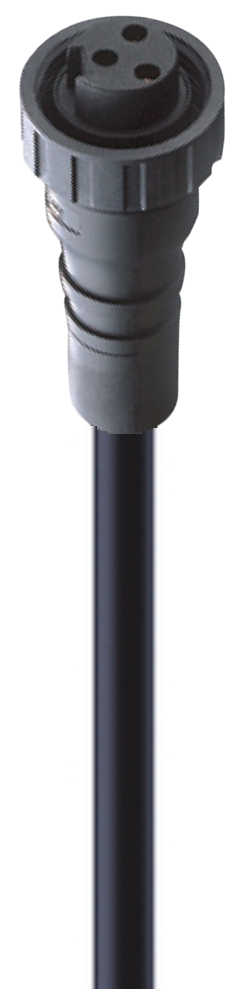
0905 203 301
DeviceNet Power Supply Cable, 7/8" Power Single-Ended Cordset: Female straight, 3-pin(2+PE), black body, 63 V, 12 A; PUR black cable, 1.00 mm2
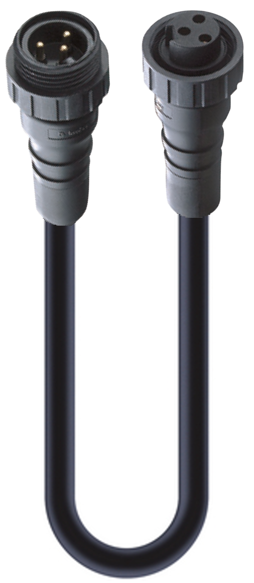
0905 203 302
DeviceNet Power Supply Cable, 7/8" Power Double-Ended Cordset: Male straight to Female straight, 3-pin(2+PE), black body, 63 V, 12 A; PUR black cable, 1.00 mm2
0906 UTP 301
Molded Tee Connector: 5 Contacts; one 7/8" Male x two 7/8" Female; 300 V | 8 A (truck) 4 A (drop)
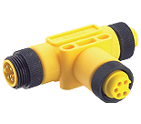
0906 UTP 301-Y
Molded Tee Connector: 5 Contacts; one 7/8" Male x two 7/8" Female; 300 V | 8 A (truck) 4 A (drop)